Abstract
The drive system constitutes the mechanical foundation upon which all CNC machining precision is built. From woodworking routers to stone carving centers, the servo motor, reducer, and feedback loop determine achievable tolerances, surface finish quality, and overall machine longevity. This article examines the technical architecture of modern CNC drive systems, presents comparative performance data across machine categories, and discusses how manufacturers like ROCLAS® MACHINERY CO., LTD. integrate these systems into industrial-grade equipment. The analysis draws on empirical data from the CNC fabrication sector to illustrate the relationship between drive system specifications and real-world machining outcomes.
---
1. Introduction: Why the Drive System Matters
In CNC machining, the drive system is often overlooked by end-users who focus primarily on spindle power or control software. Yet it is the drive system—comprising servo motors, reducers, ball screws, and linear guides—that translates digital commands into physical motion with measurable precision. A machine with an excellent spindle but a poor drive system will produce inconsistent cuts, exhibit backlash, and suffer from premature mechanical wear.
The drive system’s performance is quantified through three key parameters: positioning accuracy, repositioning accuracy, and maximum acceleration. These figures directly influence cycle times, tool life, and part quality. For applications ranging from aluminum profile cutting to granite engraving, selecting the appropriate drive configuration is not optional—it is foundational.
---
2. Drive System Architecture in Modern CNC Equipment
2.1 Servo Motor and Reducer Integration
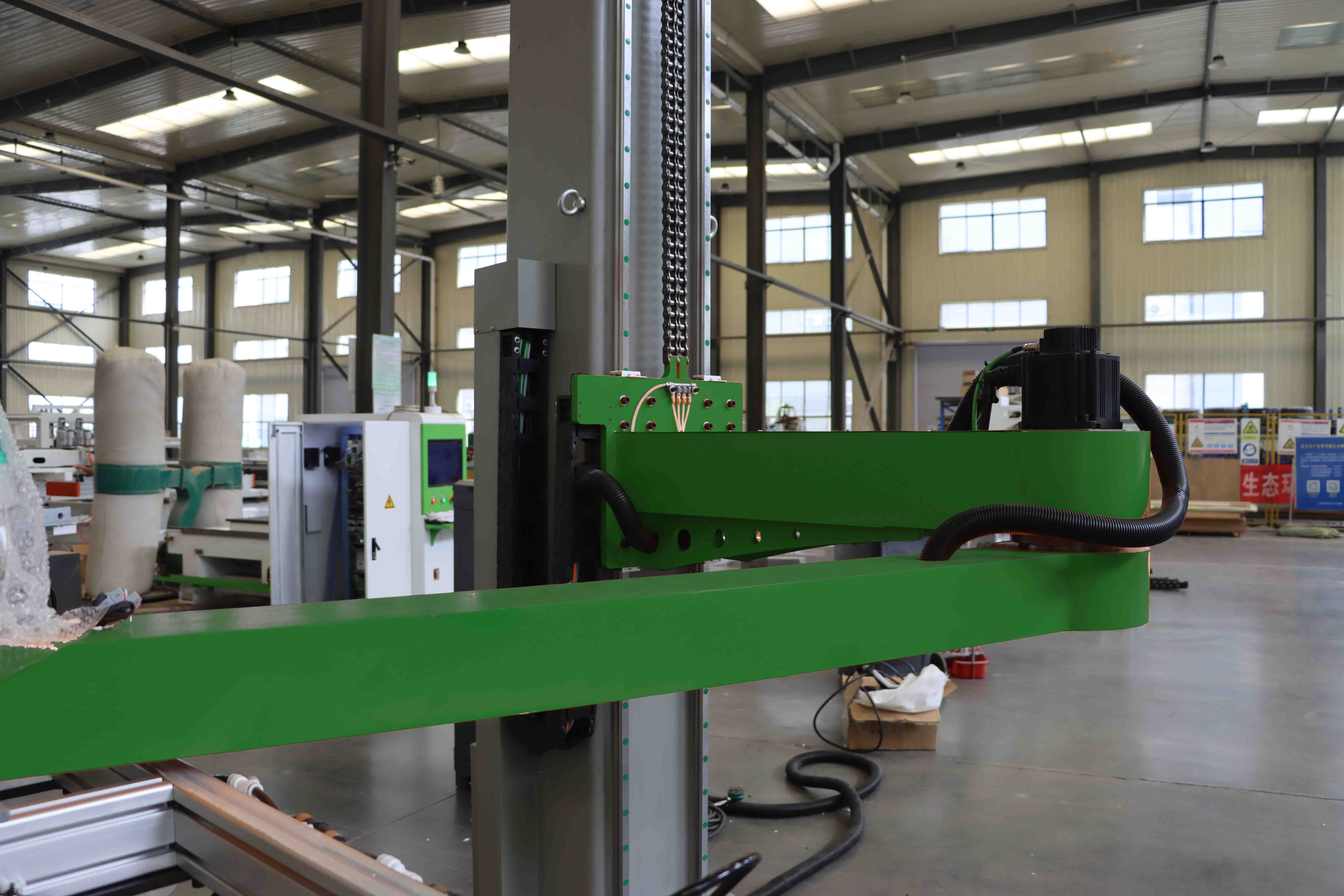
Modern CNC routers and machining centers employ closed-loop servo systems. Unlike stepper motors, which can lose steps under load, servo motors continuously report their position back to the controller. This feedback loop enables real-time error correction—a critical feature for high-precision work.
The reducer, typically a planetary gearbox, amplifies torque while reducing speed. This is especially important in stone machining, where cutting forces can exceed 500 N·m. A high-quality reducer with low backlash (≤3 arc-min) ensures that the tool path remains accurate even under heavy load.
2.2 Gantry vs. Moving Table Configurations
Two primary mechanical architectures dominate the market:
- Fixed gantry, moving table: The workpiece moves beneath a stationary gantry. This design offers superior rigidity and is preferred for heavy materials like stone and thick steel.
- Moving gantry, fixed table: The gantry traverses over a stationary workpiece. This configuration allows for larger work envelopes but requires stiffer drive components to maintain accuracy.
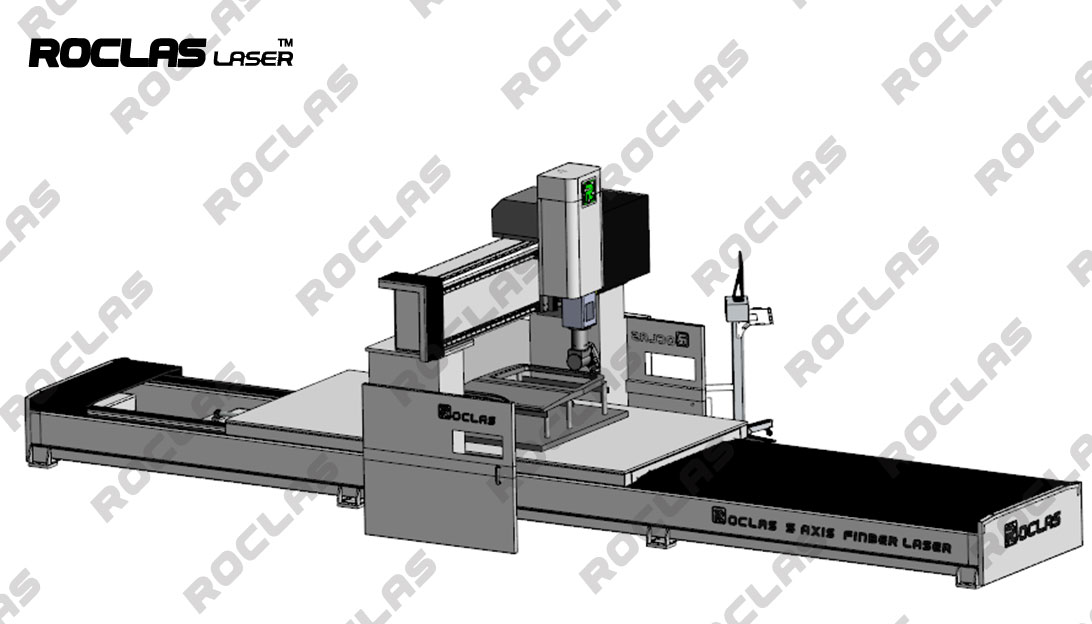
ROCLAS® MACHINERY CO., LTD., operating under the Roctech brand, employs a fixed gantry structure with movable workbench in its 5-axis fiber laser cutting centers. This design maximizes processing space while maintaining the dynamic performance required for three-dimensional cutting.
---
3. Drive System Performance Data: A Comparative Analysis
The following table presents drive system specifications across three representative machine categories. Data is compiled from industry literature and manufacturer technical documentation, including ROCLAS product sheets.
| Parameter | Woodworking CNC Router | Stone CNC Machining Center | Fiber laser cutting machine |
|-----------|------------------------|----------------------------|-----------------------------|
| X/Y Axis Positioning Accuracy | ±0.05 mm | ±0.10 mm | ±0.03 mm |
| X/Y Axis Repositioning Accuracy | ±0.03 mm | ±0.05 mm | ±0.02 mm |
| Maximum Travel Speed | 60 m/min | 30 m/min | 100 m/min |
| Maximum Acceleration | 0.5G | 0.3G | 1.0G |
| Drive Motor Type | AC Servo (1.5–3.0 kW) | AC Servo (3.0–7.5 kW) | AC Servo (1.0–2.0 kW) |
| Reducer Type | Planetary (10:1) | Planetary (20:1) | Planetary (5:1) |
| Linear Guide Type | Ball-type (H25) | Roller-type (H45) | Ball-type (H20) |
| Ball Screw Diameter | 25 mm | 40 mm | 32 mm |
| Typical Machine Weight | 1,500–3,000 kg | 5,000–12,000 kg | 3,000–6,000 kg |
| Suitable Material Hardness | Up to HRC 45 | Up to Mohs 7 | N/A (thermal cutting) |
3.1 Interpreting the Data
Several observations emerge from this comparison:
Accuracy vs. Speed Trade-off: Stone machining centers prioritize rigidity and torque over speed. Their lower travel speeds (30 m/min) and higher gear ratios (20:1) reflect the need to maintain position under high cutting forces. In contrast, laser cutting