In metal fabrication, cutting accuracy is among the most consequential specifications a machine can carry. It determines whether a component drops straight into an assembly or requires rework, and it dictates how tightly a shop can quote tolerances without inflating scrap rates. Yet the term is often used loosely. Positioning accuracy, repeat positioning accuracy, kerf width, and cut-edge quality are frequently bundled together under a single heading, which makes cross-vendor comparison unreliable. This article separates these concepts and examines how they are achieved in practice, using fiber laser platforms as the reference case.
Defining the Terms
Positioning accuracy describes how closely the cutting head arrives at a commanded coordinate. It is a static measure of the machine's ability to reach a target position. Repeat positioning accuracy describes the spread of positions when the same coordinate is commanded multiple times. A machine may position with modest absolute accuracy but excellent repeatability, which matters more in production where every part must match the previous one. Kerf width is the width of material removed by the beam, and it governs how closely nested parts can be placed and how fine internal features can be cut. Cut-edge quality covers dross adhesion, perpendicularity, and surface roughness — factors that determine whether secondary finishing is required.
These four parameters interact. A machine with ±0.03 mm positioning accuracy will not deliver a ±0.03 mm part if kerf compensation is poorly calibrated or if the beam diverges across a thick section. Accuracy at the controller is only the starting point.
Where Accuracy Is Decided
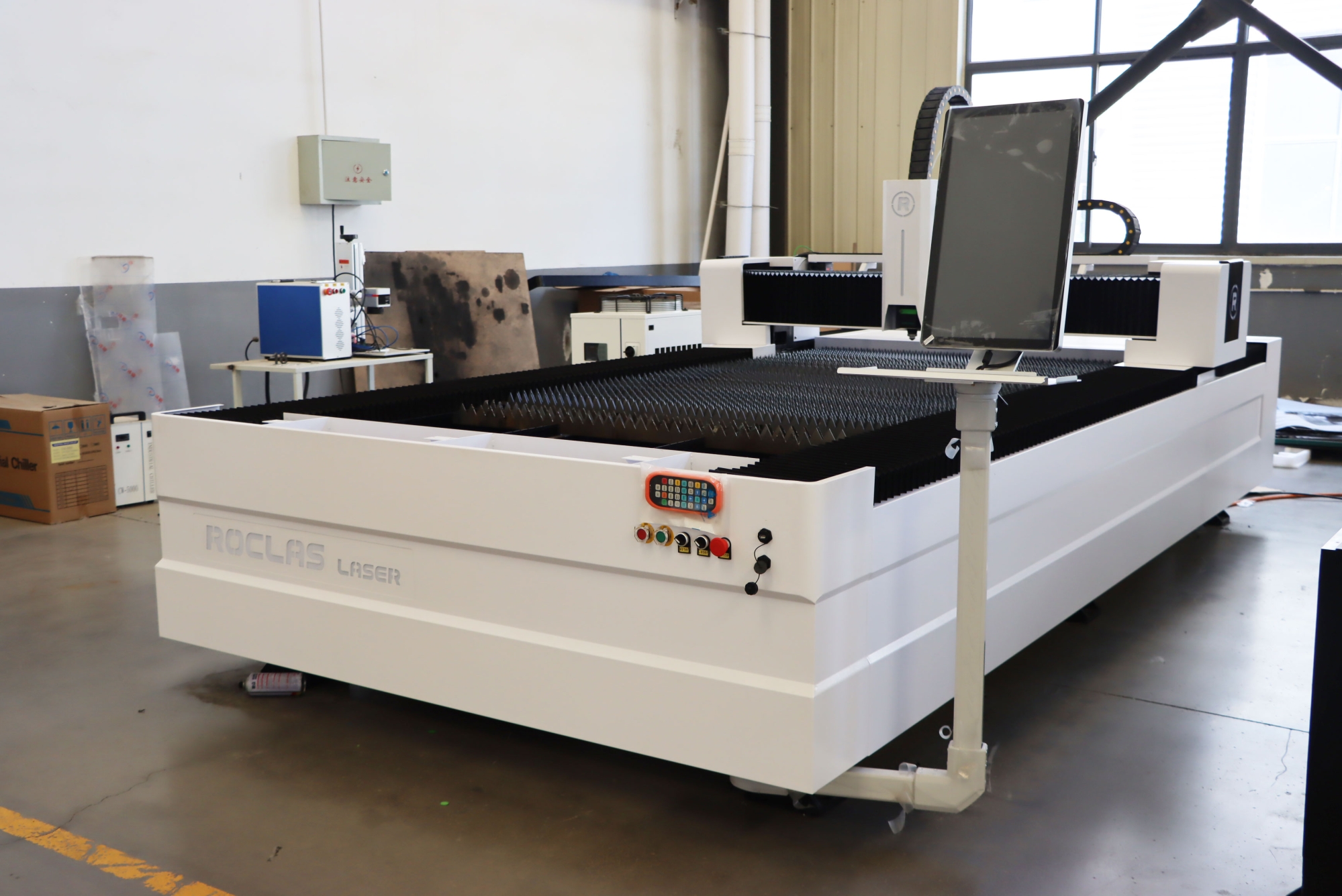
Structural rigidity is the foundation. A gantry that flexes under acceleration will produce positional error that no control algorithm can fully correct. This is why industrial-grade laser platforms use heavy-duty steel structures machined on CNC five-face machining centers — the mounting surfaces for guide rails and racks must themselves be flat and square before any motion system is installed. Imported servo drives and reducers, combined with a fixed gantry and movable workbench layout, allow travel speeds up to 100 m/min and maximum acceleration of 1.0G without sacrificing stability. High acceleration is not merely a throughput feature; it reduces the thermal load on the workpiece during contouring, which in turn limits heat-affected zone distortion.
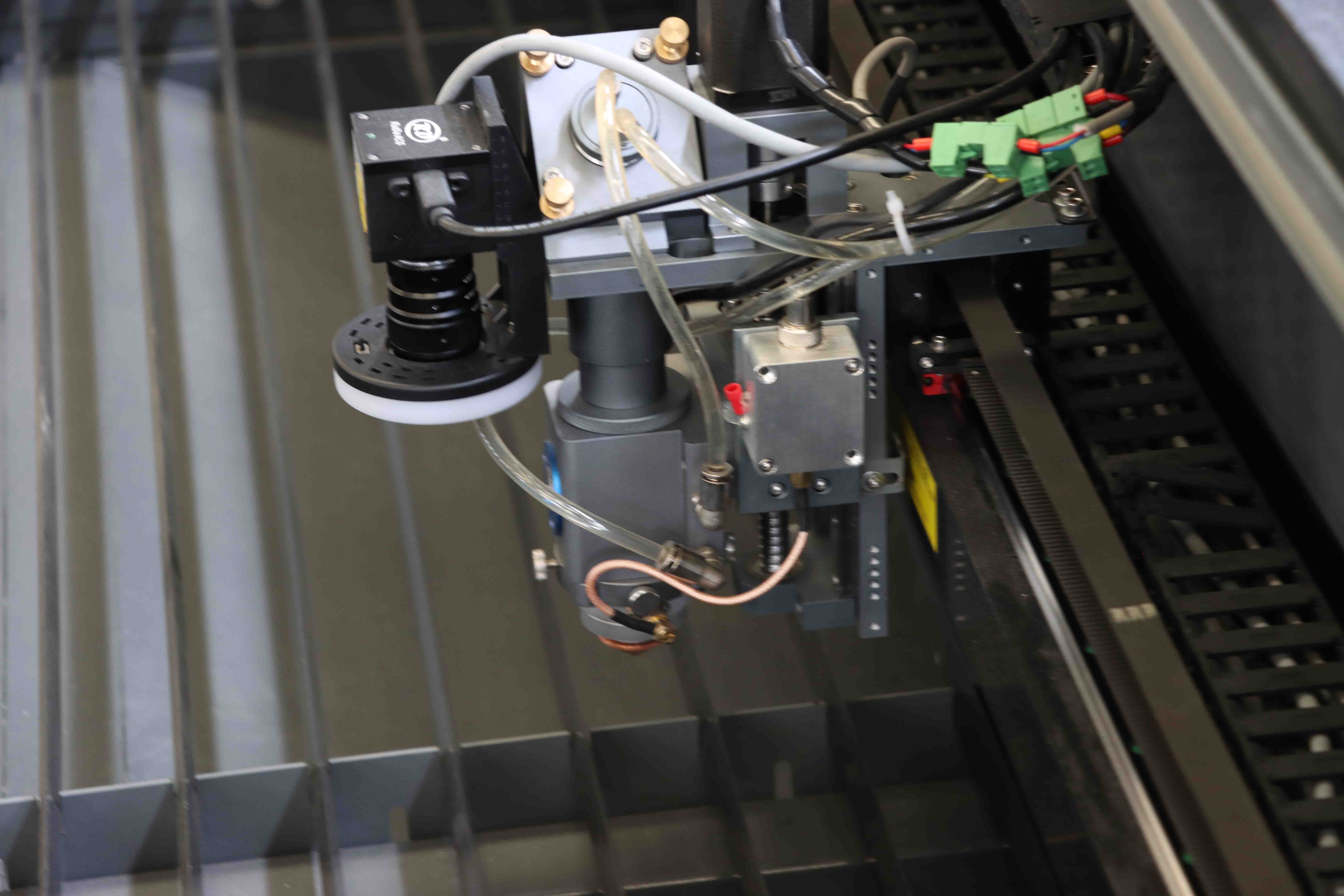
The control system translates geometry into motion. Professional CNC software such as the Cypcut 3000S handles nesting, kerf compensation, and corner control, applying reduced feed rates at tight radii to prevent rounding. Laser head selection matters as well; Raytools cutting heads with automatic focus adjustment maintain consistent spot size as material thickness changes.
Representative Specifications
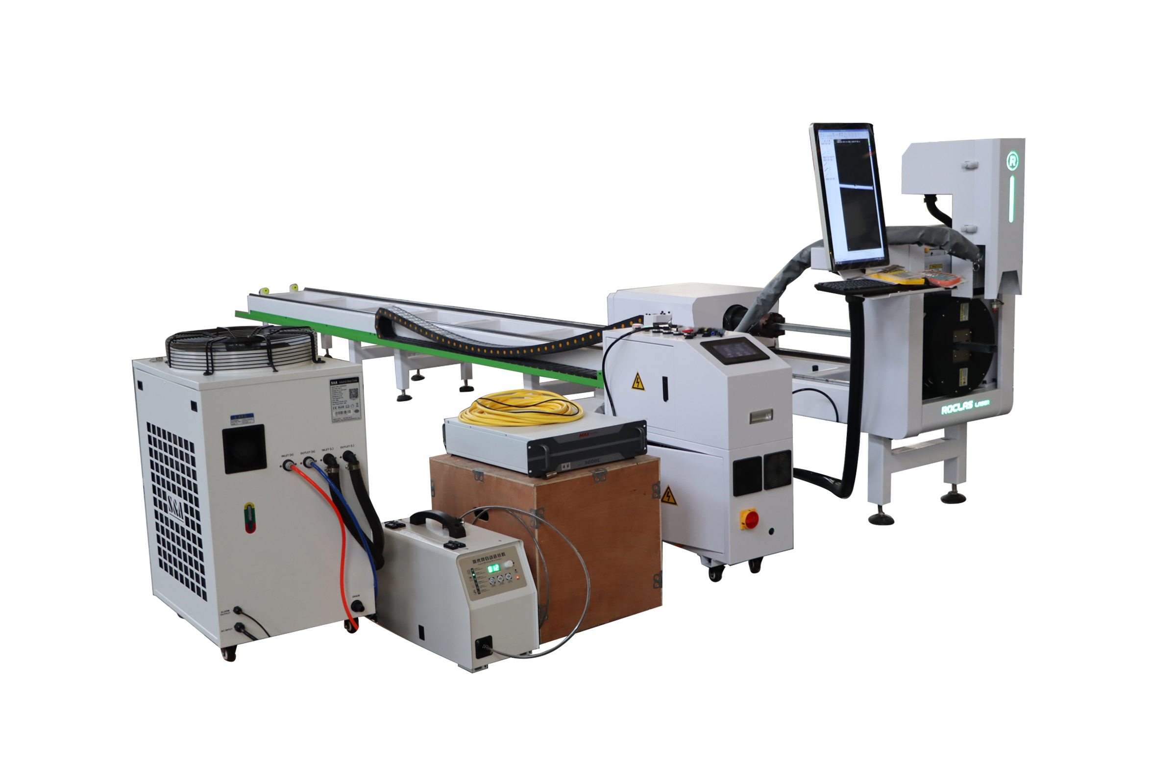
The table below summarizes accuracy-related parameters across typical fiber laser configurations. Values reflect standard sheet metal machines and dedicated tube cutting platforms.
| Parameter | Sheet Metal Machine | Tube Cutting Machine |
|---|---|---|
| Positioning accuracy (X/Y) | ±0.03 mm | ±0.05 mm |
| Repeat positioning accuracy | ±0.02 mm | ±0.03 mm |
| Travel speed | 100 m/min | 100 m/min |
| Max acceleration | 1.0G | 1.0G |
| Laser power range | 1 kW – 20 kW | 1 kW – 3 kW |
| Max tube diameter | — | 220 mm |
| Control system | Cypcut 3000S | Cypcut 3000S |
The data reveal a deliberate distinction between flat sheet and tube processing. Sheet metal cutting holds tighter tolerances because the workpiece is supported across the bed and thermal paths are predictable. Tube cutting introduces rotational axes and chuck clamping variables, so ±0.05 mm positioning is a realistic and honest figure rather than a marketing number. Note also that repeat accuracy is consistently tighter than absolute accuracy — a design choice that favors production consistency over one-time metrology.
Power range deserves comment. A 20 kW source cuts thick plate efficiently, but accuracy does not scale with power automatically. Higher power widens the kerf if focus and gas pressure are not re-optimized, so the accuracy specification applies across the power band only when process parameters are matched to thickness.
Material Behavior and the Limits of Specification
Accuracy figures are typically quoted for mild steel under ideal conditions. Real production involves stainless steel, aluminum, copper, brass, galvanized steel, and titanium, each with different thermal conductivity and reflectivity. Highly reflective metals such as copper and aluminum reflect beam energy back toward the optics, which can destabilize the cut and degrade edge quality. Machines equipped with a high-reflectivity suppression module can process 1–2 mm copper and 2–3 mm aluminum stably, but the achievable accuracy on these materials is bounded by heat dissipation rather than by the motion system.
Non-metal processing follows different rules. Hybrid CO2 and fiber platforms handle acrylic, wood, leather, and fabric, where the cutting mechanism is thermal decomposition rather than melt ejection. On a 1500 × 3000 mm working area, edge quality depends heavily on assist gas and feed rate, and tolerances are typically looser than for metals.
The Brand Perspective
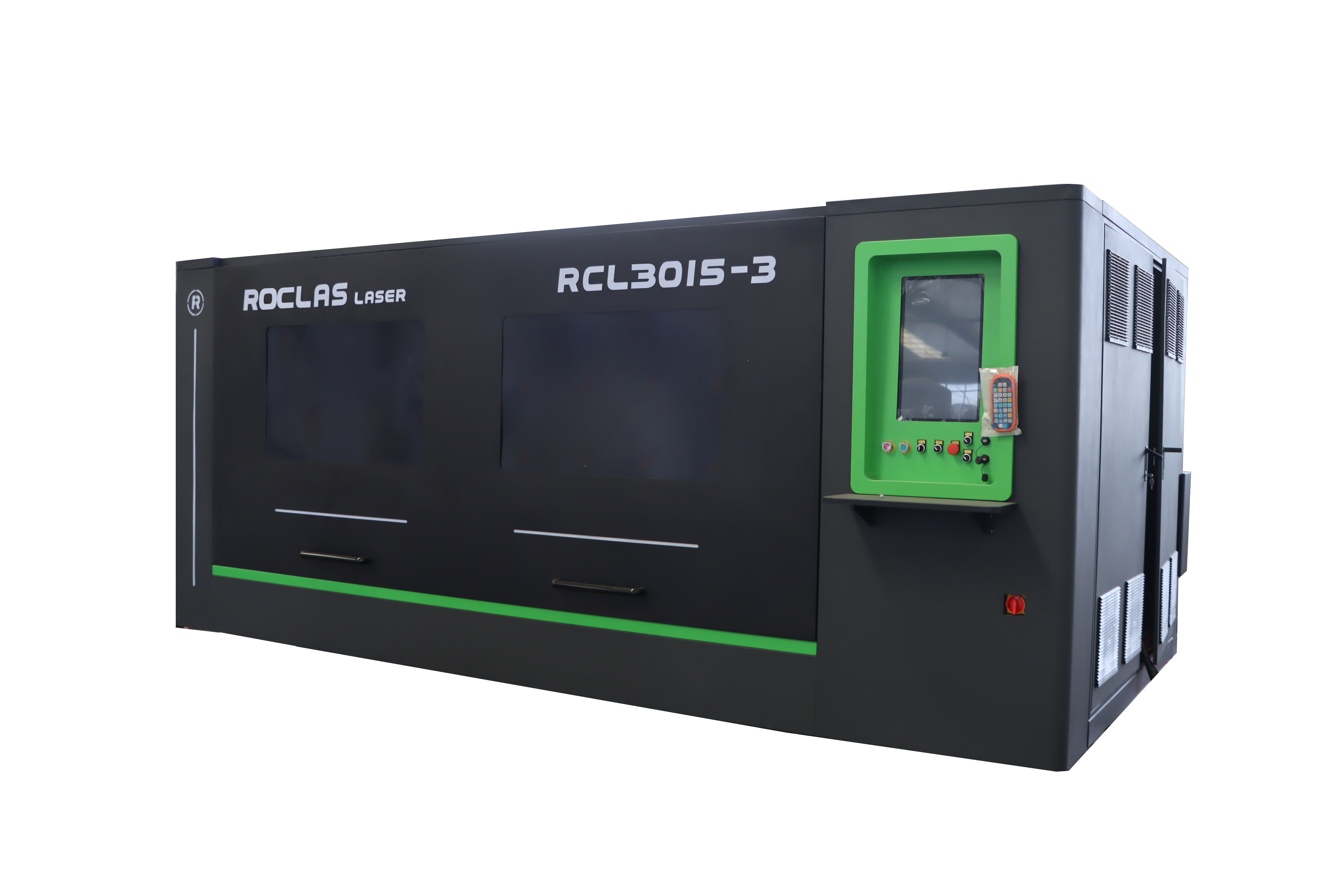
ROCLAS® MACHINERY CO., LTD. illustrates how accuracy specifications are backed in practice. With more than 15 years in the industry, a 15-member R&D team, and over 50 patents — with 10 or more added annually — the company positions accuracy as an outcome of manufacturing discipline rather than a single component choice. Its Fiber laser cutting machines span 1000 W to 20 kW using Raycus or MAX sources, and the 5-axis platform adds n×360° infinite rotation for three-dimensional workpieces, extending the accuracy conversation into complex geometry. Certifications including ISO 9001, CE, FDA, UL, and PDL provide third-party verification that claimed tolerances are reproducible under audit. For buyers, this matters: a tolerance printed on a datasheet is a claim, while a certified and repeatable tolerance is a capability.
Practical Guidance
When evaluating cutting accuracy, request a test cut on the material and thickness you actually run, not on mild steel coupons. Measure both absolute position and repeatability across a batch. Inspect kerf width and dross on internal corners, where acceleration limits are most visible. Finally, confirm that the machine's structural design — welded or modular screw-connected bed, both of which ROCLAS offers with equivalent manufacturing quality — suits your transport and installation constraints without compromising rigidity.
Cutting accuracy is not one number. It is the sum of structural design, motion control, process tuning, and material behavior. Understanding which component limits your application is the difference between a specification sheet and a working process.